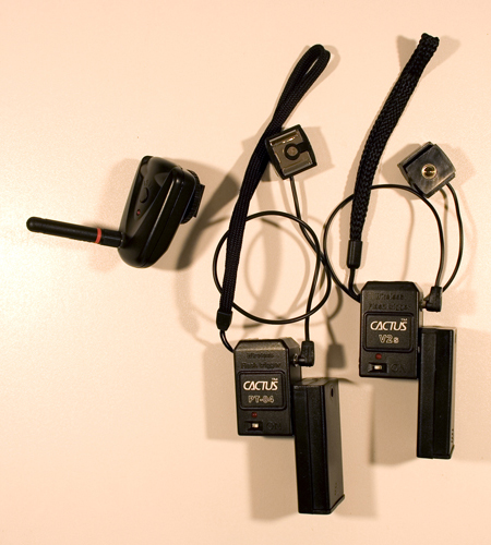
And now I present to you, my tutorial for modifying the 'ebay' triggers.
Before I go too far though, there are a few things I need to mention. First (and probably foremost), I cannot be held responsible for any damage done to any transmitters/receivers while attempting these modifications. That said, there are certain skills required to do this correctly. Soldering being the most obvious and probably most difficult. I am no master at soldering, but make sure you know how to correctly solder before attempting this. Here is a good place to start learning or refresh yourself if you aren’t sure. You’ll also need to be able to drill steadily. Very important in that there are times when the drill will come close to the circuit board, and circuit boards don’t generally take well to spinning drill bits.
Next I’ll go over the supplies needed:
Tools:
-Drill
-Drill bits (I used a 3/16 and a 3/32)
-Soldering Iron
-Needle nose pliers
You’ll also need solder, wire (I used stranded copper wire), and epoxy.
For the actual modifications:
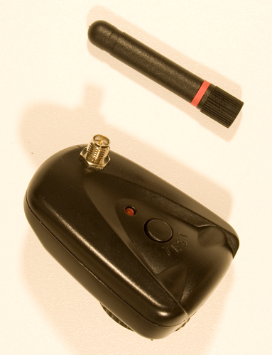
-433Mhz Antenna
I bought this from http://www.digi-key.com/, product #ANT-433-CW-RH, approximate price $6.32. It’s a 433MHz ¼ Wave Whip Antenna with an RP-SMA connection, allowing it to be connected and disconnected as needed so it doesn’t get snapped off in your camera bag. Because of this, you’ll also need…
-RP-SMA Connector
I bought this at the same site, product # CONREVSMA004, approximate price $3.22.
-Lanyard
I grabbed a lanyard for each receiver from random electronics around my house. They generally come with cell phones, mp3 players, and lots of other random small electronics (including many small digital cameras), so finding 2 wasn’t difficult for me. If you need to buy them, I know they sell them at places like Ritz/Wolf camera, but they’re probably ridiculously priced. You’re on your own for finding them though.
-2xAA
This I bought from the local Radio Shack. It’s an enclosed battery holder for 2 AA batteries. Technically you could use the 2xAAA battery holder too, but I really don’t see the point. The reason I got the enclosed case was for a more professional look. In the end there are no exposed wires, and the look is much nicer than the exposed battery cases. The price on these is right around $1.90 each I believe.
That’s all of the equipment/supplies needed. The antenna and connector came out to $15.59 with S&H (there’s a $5 charge for orders under $25), and I just picked up the battery cases locally. All told, under $20 for the supplies, plus costs of any tools and expendable supplies (i.e. wire, epoxy, etc.). This put my total cost with the transmitter and 2 receivers (plus S&H) at right around $82.
Now for the real meat of the tutorial. I’ll start with the transmitter antenna modification, as it is probably the most important in terms of the modification itself and the results it garners. Make sure to read through the whole tutorial before you start the work. And make sure to remove all batteries before as well.

To begin, you’ll have to drill the hole for the connector through the top plate of the transmitter. This seems simple, but in reality is probably the most difficult part for the mod, simply because there is limited room. If the hole is too close to the front, the connector won’t fit. If it’s too close to the back, it’ll hit the circuit board and again, won’t fit. Measure twice, cut once. It may help to drill a starter hole and move from there. I used the 3/16 bit, though in actuality it needs to be a bit larger hole than that. All I did was shave off small sections from the hole to make it bigger, so I honestly can’t tell you if a ¼ bit will work perfectly or not, but I suspect it would. I put the hole about 7/16” from the front, and 3/8” from the side with the 2.5mm jack. You can test the fit of the connector, but don’t yet mount it in.
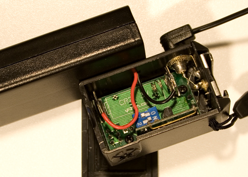
Next, solder about 3 inches of wire to the bottom of the connector. Do this before you mount the connector, as it will be easier to keep from melting the plastic, unless you’re confident in your steady hand. I say 3” of wire because then you can cut to length before soldering the other end into the circuit board. When soldering the wire to the connector, you will probably have to solder it in a loop around the pin on the connector in order to allow the assembly to fit inside the transmitter, as shown.
Once the wire is soldered to the connector, go ahead and mount the connector to the top plate using the mounting nut that comes on the connector. After that, you’re ready to get the wire ready to be soldered to the circuit board. You’ll want to make sure you have enough room that it won’t be a stretch and won’t get in the way of the center post (where the top plate is screwed to the bottom plate), but not so much wire that there’s lots of extra in the transmitter.
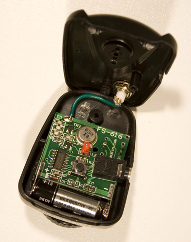

Once you have the wire cut to length and the end stripped, go ahead and solder the wire to the open, tinned hole on the circuit board (near the front, opposite the side with the 2.5mm jack).
********EDIT********
 Another Strobist follower, vaddzagg, came up with an alternative method for the internal wire used to connect the antenna to the circuit board:
He used a length of wire equal to 1/4 wavelength of 433Mhz, in order to make the entire antenna including the wire a 1/2 wave antenna. He found that this improved his transmitter a bit more, you can send him mail via flickr here.
*********************
With that complete, your antenna mod should be done. All that is left is to attach the top plate, and screw in the antenna itself into the connector. This modification alone should give you a great boost to distance and reliability.
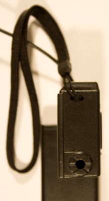
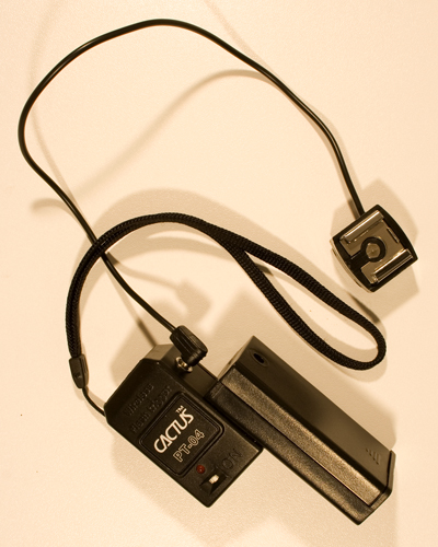
The next modification will be the simplest, the lanyard for the receivers. All I did for this was to drill two small holes near the top of the receiver on the side opposite the PC jack. I used the 3/32 bit, and drilled the holes about 3/32” apart from each other. Be careful with the drill, as if you go too far into the receiver after pushing through the case, you’ll hit wire. I then threaded the end of the lanyard in one hole and out the other (using a wire leader to pull it through), and attached the lanyard as shown. Easy modification, and now you can hang the receiver from anywhere you can hang a Pocket Wizard.

The last modification is the external battery pack for the receiver. This will increase the life of the receiver during a shoot, and also decrease the cost of batteries for the receiver (2 AA batteries versus the $10 CR2 3V batteries). As an aside, I use regular AA batteries instead of rechargeable batteries, so I have no idea how rechargeable batteries will work. I can’t imagine it would make much of a difference, but I’m just letting you know.
The first step in the battery mod is to get the case ready to be attached to the receiver. To do this, begin by simply removing the cover with a small Phillips-head screwdriver. Inside you’ll notice where the two wires come into the case and are soldered to small metal plates at the top of the case. Use the needle nose pliers to gently pull the plates out of the plastic case. They’ll put up a small fight, but be gentle and they’ll come out easy enough. Once they’re free of the case, pull them both out with the wires attached. We’ll put them back in later.
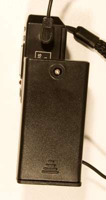
Now the case is ready to be attached to the receiver with some epoxy. First, line up the case exactly where you’ll want it on the receiver. If you look at my photos, you’ll see that I’ve attached it to the same side as the PC jack, about half way down the side and flush with the front of the receiver. At this location, the hole that we’ll drill will be in a convenient spot so as not to interfere with the spring or the circuit board inside. Once you have the location you want, you’re ready to epoxy. Remember that you want to epoxy the back of the battery case, not the front where the screw is to open it. Epoxy is very strong stuff, so you don’t need to overdo it (read: A little dab will do ya!). Put some epoxy on both the receiver and the battery case, and hold them in place until they set a bit and you can let them dry on their own. Once it’s dried and cured, you’re set to move on to the next step.
Next you’ll drill the hole through both cases to allow the wires to move through from the battery case to the receiver. When you’re drilling the hole, remember again to measure twice, cut once. The hole needs to be far enough from the front of the receiver so as to not hit the circuit board, but not so far it’s outside the receiver altogether. I found that the best place for the hole just happened to be where there’s a nice little post inside the battery cover (just to the left of the center post where the screw for the battery case cover goes). So I managed to grab something to wedge the post out (it comes off/out pretty easy, just use a flat head screwdriver or something similar), and then used that mark to drill the hole. I used the 3/32 bit again, but it’s a pretty tight fit for the wires. It should work, you just may have to shave a side of the hole a bit to give yourself a little extra room. Go VERY slow with this drilling, too fast and once you push through the case you’ll push through circuitry. And then all is for naught. So BE CAREFUL.
Once the hole is drilled, we can put the wires back into the case. First push the ends of the wires (opposite the ends soldered to the metal plates) through the new hole into the receiver. Pull them through a little ways and then set the metal plates back into their positions in the battery case, just as they were before they were pulled out. They should stay put pretty well, but if you want you can put a little superglue at the corners to keep them there (I didn’t bother, they friction fit just fine by me). Once the plates are in, pull the wires in the rest of the way, being careful to make sure they sit in the battery case well. Now we’ll get the wires ready to be soldered in the receiver.
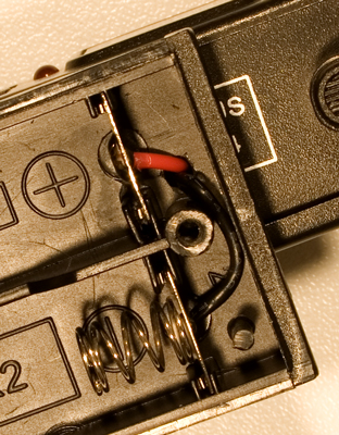
First, we want to make sure we’re soldering the correct wire in the correct place. The red wire is positive, black is negative. If you don’t already know this, put down the soldering iron and step away. Just kidding. But not really.
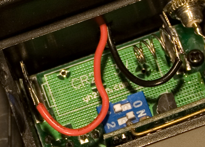
The black wire is going to be soldered to the top of the metal plate with the spring attached, and the red wire will be soldered to the opposite plate. Before soldering, cut the wires to a manageable length such as shown in the photo. Once the length is correct, you’ll simply solder the wires in place. This can get a little tricky as you don’t want to melt the plastic of the case or touch any other circuitry, but very doable. Just try to bend and place the wire so it sits on the metal plate on its own before soldering.
Once you’ve got the wires soldered in correctly, you should be good to go. Throw a couple AA batteries in the case, put both covers on, and that’s it!
That should be it for all three modifications. Just make sure to take your time and do it right, and I think you’ll be very pleased with the results. There may be more modifications in the future, I’m always trying to make the equipment I have better in whatever ways I can. I hope this helps, if you have any questions don’t hesitate to ask. My Flickr account is ‘kuster’, and my email address is jeremy@jeremykuster.com. Let me know how it turns out (unless something goes wrong :-P).